Here’s my journey in the Kerala IoT Challenge
About me
Hey! I’m A R Rahman. I’m a second year CSE student from AISAT Kalamassery.
Experiment 1
Hello World LED Blinking
ITEMS NEEDED:-
- Arduino UNO
- A Breadboard
- Male to male jumper wires (x2)
- LED
- USB cable to connect the arduino
- Resistor
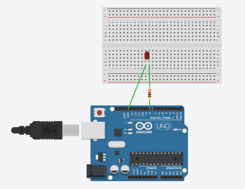
Circuit Diagram:
Code:
 void setup()
{
  pinMode(8, OUTPUT);
}

void loop()
{
  digitalWrite(8, HIGH);
  delay(1000); // Wait for 1000 millisecond(s)
  digitalWrite(8, LOW);
  delay(1000); // Wait for 1000 millisecond(s)
}
Output:
We have an LED which blinks every second.
Experiment 2
Traffic Light
ITEMS NEEDED:-
- Arduino UNO
- A Breadboard
- Male to male jumper wires (x4)
- LED (Red,Yellow,Green)
- USB cable to connect the arduino
- Resistors (3x)
Circuit Diagram:

Code:
int redled =10; // initialize digital pin 8.
int yellowled =7; // initialize digital pin 7.
int greenled =4; // initialize digital pin 4.
void setup()
{
pinMode(redled, OUTPUT);// set the pin with red LED as “output”
pinMode(yellowled, OUTPUT); // set the pin with yellow LED as “output”
pinMode(greenled, OUTPUT); // set the pin with green LED as “output”
}
void loop()
{
digitalWrite(greenled, HIGH);//// turn on green LED
delay(5000);// wait 5 seconds

digitalWrite(greenled, LOW); // turn off green LED
for(int i=0;i<3;i++)// blinks for 3 times
{
delay(500);// wait 0.5 second
digitalWrite(yellowled, HIGH);// turn on yellow LED
delay(500);// wait 0.5 second
digitalWrite(yellowled, LOW);// turn off yellow LED
}
delay(500);// wait 0.5 second
digitalWrite(redled, HIGH);// turn on red LED
delay(5000);// wait 5 seconds
digitalWrite(redled, LOW);// turn off red LED
}
Output:
We have three LEDs which act as traffic lights namely RED, YELLOW and GREEN which goes in such a way that the green glows for 5 seconds, then the yellow starts blinking followed by which the red light comes up which also stays lit for around 5 seconds, proceeding which the green light starts glowing again which continues a cycle.
Experiment 3
LED Chasing Effect
ITEMS NEEDED:-
- Arduino UNO
- A Breadboard
- Male to male jumper wires (x7)
- LED (x6)
- USB cable to connect the arduino
- Resistors (6x)
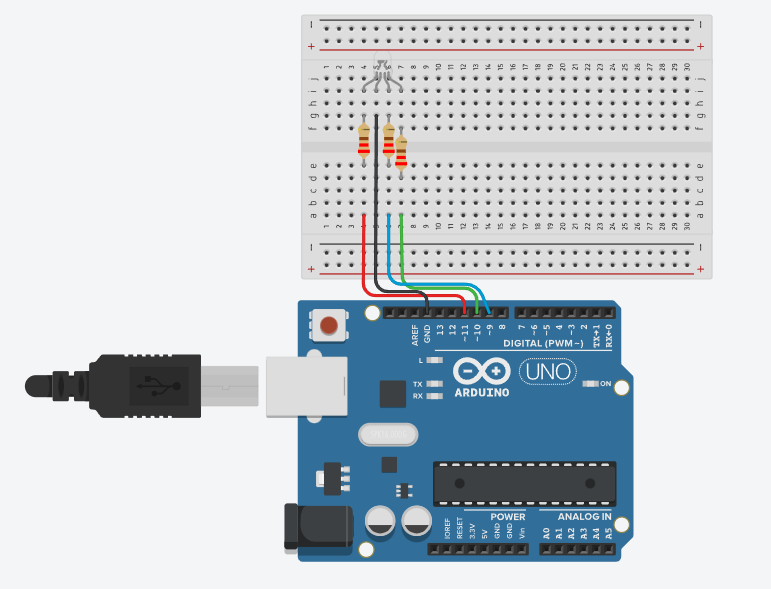
Circuit Diagram:

Code:
int BASE = 2 ;  // the IO pin for the first LED
int NUM = 6;   // number of LEDs
void setup()
{
   for (int i = BASE; i < BASE + NUM; i ++)
   {
     pinMode(i, OUTPUT);   // set I/O pins as output
   }
}
void loop()
{
   for (int i = BASE; i < BASE + NUM; i ++)
   {
     digitalWrite(i, LOW);    // set I/O pins as “low”, turn off LEDs one by one.
     delay(200);        // delay
   }
   for (int i = BASE; i < BASE + NUM; i ++)
   {
     digitalWrite(i, HIGH);    // set I/O pins as “high”, turn on LEDs one by one
     delay(200);        // delay
   }
}
Output:
We get a chasing effect of a set of LEDs which could be compared to old billboards which had colourful LEDs with lighting effects.
Experiment 4
Button Controlled LED
ITEMS NEEDED:-
- Arduino UNO
- A Breadboard
- Male to male jumper wires (x5)
- LED (x1)
- USB cable to connect the arduino
- Resistors (10k ohm and 220 ohm)
- Button switch
Circuit Diagram:

Code:
void setup()
{
  pinMode(2, INPUT);
  pinMode(12, OUTPUT);
}

void loop()
{
  if (digitalRead(2) == HIGH) {
    digitalWrite(12, HIGH);
  } else {
    digitalWrite(12, LOW);
  }
  delay(10); // Delay a little bit to improve simulation performance
}
Output:
We get an LED which lights up when the button is pressed.
Experiment 5
Buzzer
ITEMS NEEDED:-
- Arduino UNO
- A Breadboard
- Male to male jumper wires (x2)
- A Buzzer
- USB cable to connect the arduino
Code:
void setup()
{
  pinMode(8,OUTPUT);
}
void loop()
{
digitalWrite(8, HIGH);
}
Output:
A buzzer starts producing sound
Experiment 6
RGB LED
ITEMS NEEDED:-
- Arduino UNO
- A Breadboard
- Male to male jumper wires (x4)
- RGB LED (x1)
- USB cable to connect the arduino
- Resistors
Circuit Diagram:
Code:
void setup()
{
  pinMode(11, OUTPUT);
  pinMode(10, OUTPUT);
  pinMode(9, OUTPUT);
}

void loop()
{
  analogWrite(11, 255);
  analogWrite(10, 0);
  analogWrite(9, 0);
  delay(1000);
  analogWrite(11, 0);
  analogWrite(10, 255);
  analogWrite(9, 0);
  delay(1000);
  analogWrite(11, 0);
  analogWrite(10, 0);
  analogWrite(9, 255);
  delay(1000);
}
Output:
LED starts glowing alternatively with the colors Red, Green and Blue.
Experiment 7
LDR light sensor
ITEMS NEEDED:-
- Arduino UNO
- A Breadboard
- Male to male jumper wires (x5)
- RGB LED (x1)
- USB cable to connect the arduino
- Resistors
- LDR
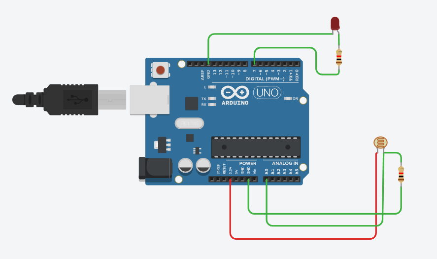
Circuit Diagram:
Code:
void setup()
{
  pinMode(A0, INPUT);
  Serial.begin(9600);

  pinMode(10, OUTPUT);
}

void loop()
{
  Serial.println(analogRead(A0));
  if (analogRead(A0) < 400) {
    digitalWrite(10, HIGH);
  } else {
    digitalWrite(10, LOW);
  }
  delay(10);
}
Output:
LED is off when there is light, when it is in the dark the LED lights up.
Experiment 8
Flame Sensor
ITEMS NEEDED:-
- Arduino UNO
- A Breadboard
- Male to male jumper wires (x5)
- Buzzer
- USB cable to connect the arduino
- Resistor
- Flame Sensor
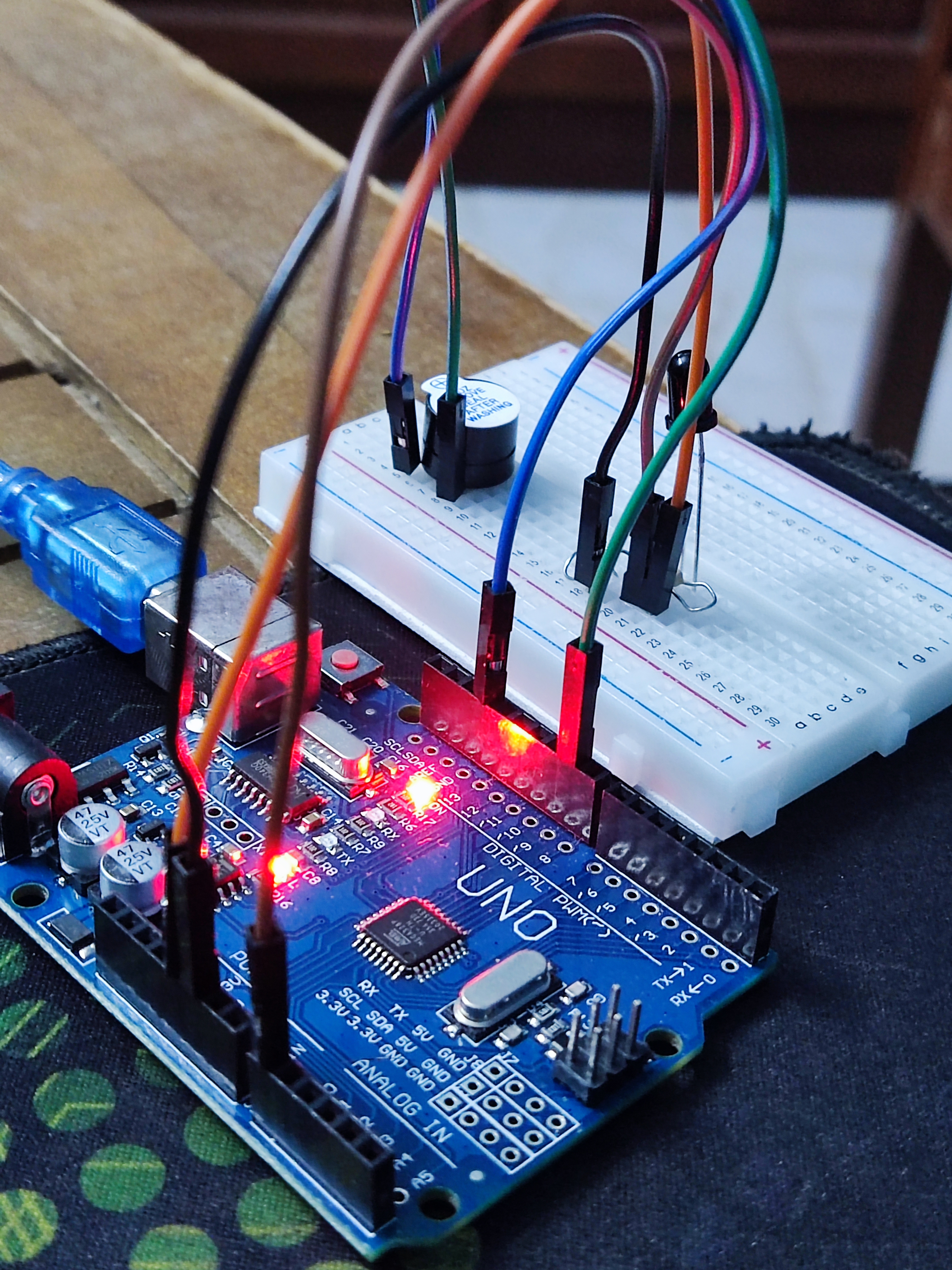
Circuit:
Code:
int flame=0;
int Beep=9;
int val=0;
 void setup()
{
  pinMode(Beep,OUTPUT);
 pinMode(flame,INPUT);
 Serial.begin(9600);
 }
void loop()
{
  val=analogRead(flame);
  Serial.println(val);
  if(val>=500)
  {
   digitalWrite(Beep,HIGH);
   }else
   {
     digitalWrite(Beep,LOW);
    }
   delay(500);
}
Output:
When you apply flame/heat to the Flame sensor, the analog value of the input gets increased. When this goes over a certain level, the buzzer starts buzzing.
Experiment 9
Temperature Sensor
ITEMS NEEDED:-
- Arduino UNO
- A Breadboard
- Male to male jumper wires (x3)
- Temperature sensor
- USB cable to connect the arduino
- Serial monitor
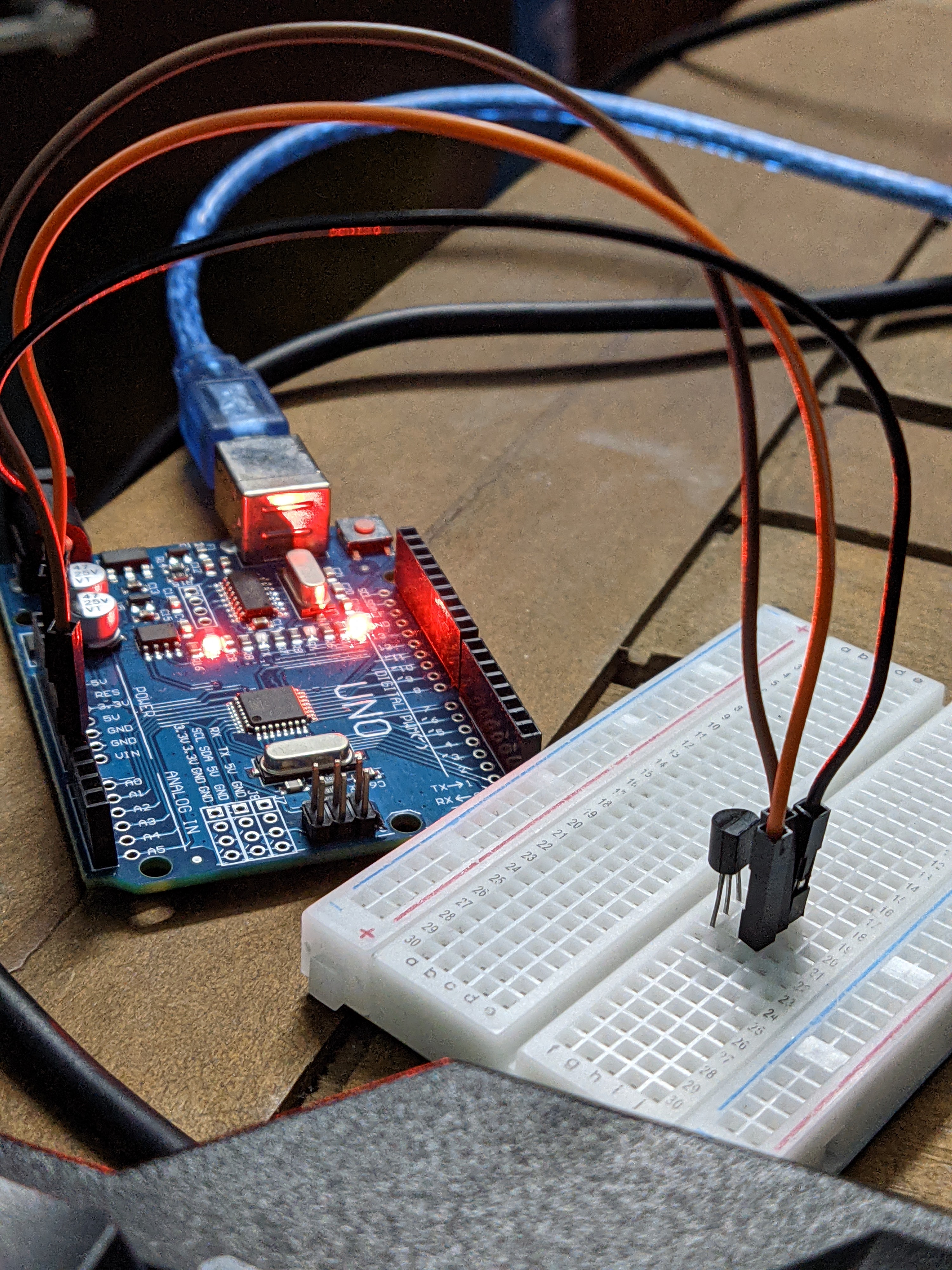
Circuit:
Code:
int potPin = 0;
void setup()
{
Serial.begin(9600);
}
void loop()
{
int val;
int dat;
val=analogRead(0);
dat=(150*val)>>8;
Serial.print("Tep");
Serial.print(dat);
Serial.println("C");
delay(500);
}
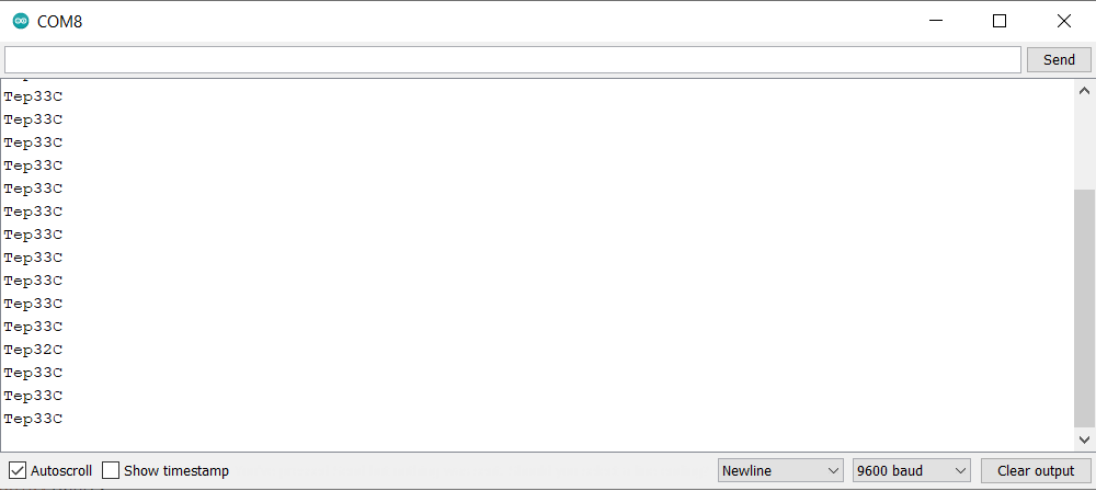
Output:
The temperature of the surroundings will be constantly be displayed on the serial monitor. In this case, we use the serial monitor on the arduino application itself.